

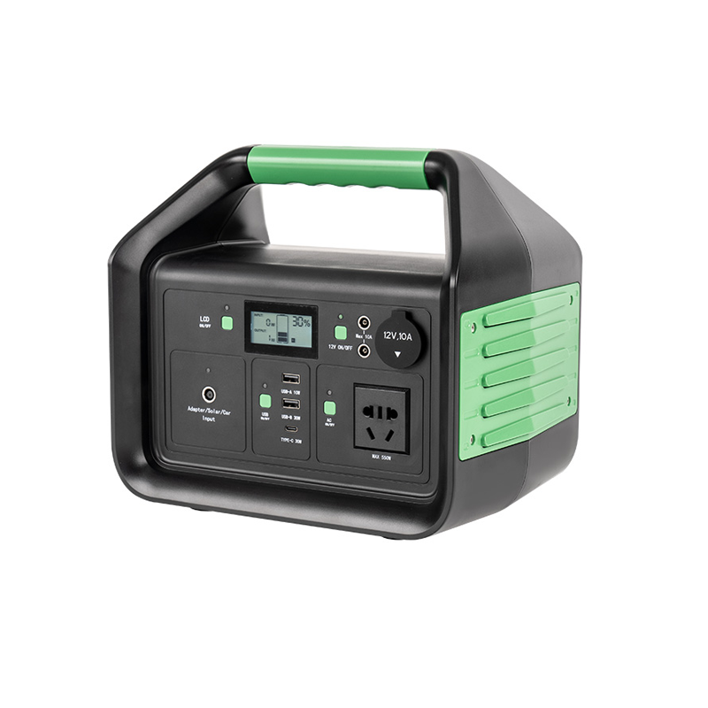
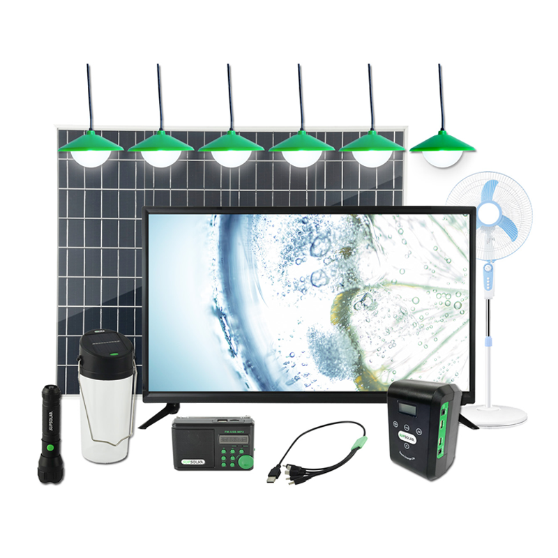
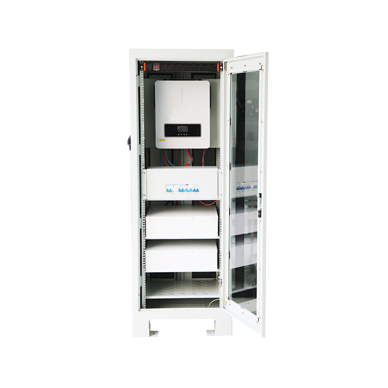
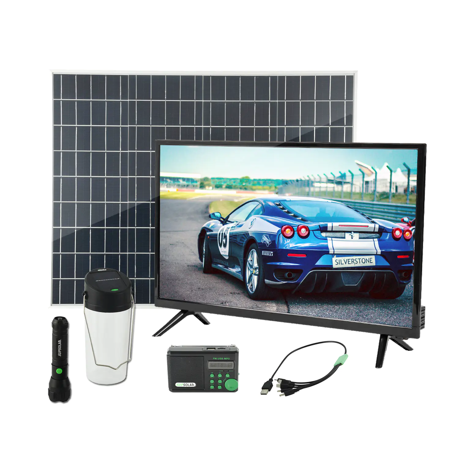

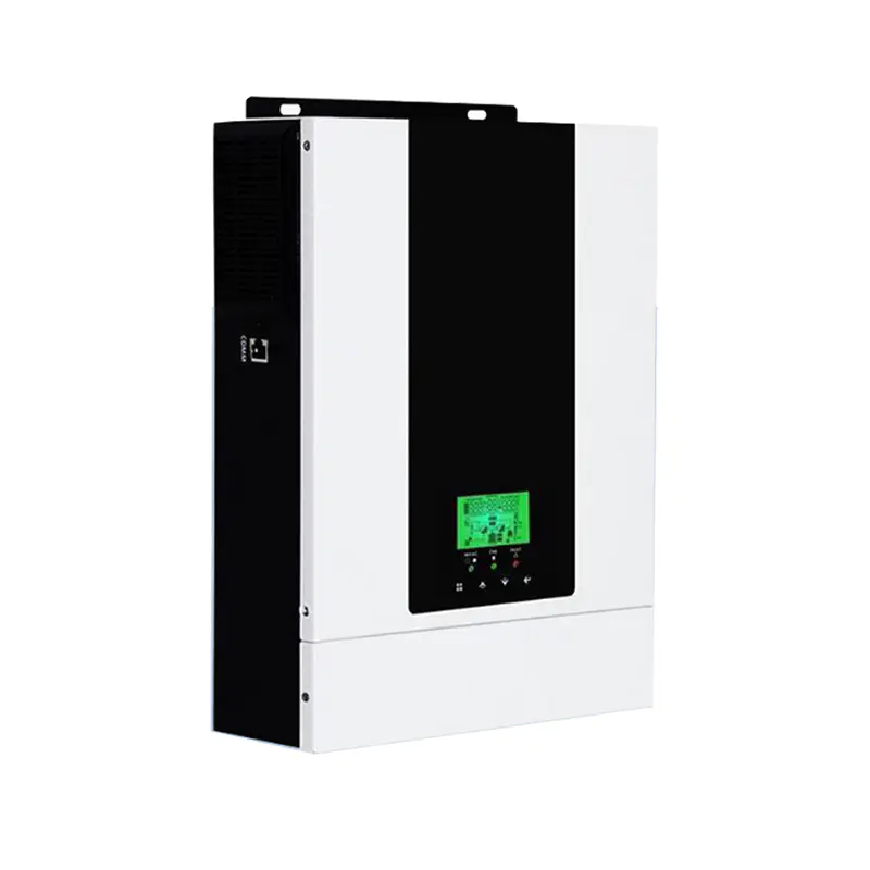
Inverter ALLTOP-STN30224
Solar inverter is a critical component in solar power systems, converting the direct current (DC) electricity gener...
Every 24V solar system starts with one decision: how to connect the panels and batteries. If you wire two 12V panels in parallel into a 24V battery bank, you will not charge that bank. You will sit at roughly 12V and risk a charge controller that never enters bulk mode. The fix is to wire those panels in series, which doubles the voltage to approximately 24V when the sun is strong. That is the core principle behind any 24 volt solar panel wiring diagram, and it is why series connections dominate in this voltage class.
When you choose a 24V system, you are already making a trade-off. Compared with a 12V system, the same power takes less current. Lower current means thinner cables and smaller voltage drops. But that benefit only appears if your solar array actually produces 24V at the controller. The common mistake is treating “24V” as a label rather than an electrical condition.
Here is the practical rule: a nominal 24V battery bank is usually made from two 12V batteries in series. A nominal 24V solar panel array can be made from two 12V panels in series, or from four 12V panels in a series-parallel grouping. If you are using true 24V panels, you may only need one panel, but most off-grid installers use 12V panels because they are cheaper and easier to replace.
The table below summarizes the consequences of each common pattern for a 24V target.
| Wiring Pattern | Panel Configuration | Output Voltage | Output Current | Fit for 24V Solar System |
|---|---|---|---|---|
| Series | Two 12V panels | 24V Vmp | Same as one panel | Yes, ideal |
| Parallel | Two 12V panels | 12V Vmp | Double one panel | No, will not charge 24V bank |
| Series-Parallel | Four 12V panels (two in series, then two pairs in parallel) | 24V Vmp | Double one panel | Yes, commonly used |
| Series only | Two 24V panels | 48V Vmp | Same as one panel | No, too high for a 24V battery system |
 off-grid solar power systemsAn off-grid solar power systems is a self-sufficient system that operates independently from the utility grid, utilizing solar panels to generate electricity. It can p...View Product →
Your 24 volt solar panel wiring diagram is only useful when every component tolerates the voltage and current. The first item is the solar charge controller. For a 24V battery bank, a PWM controller must accept an input voltage above the battery voltage. An MPPT controller is more forgiving, and it can take an array voltage well above 24V so that the panels provide more current in low light. Choose an MPPT with a maximum PV voltage at least 20% higher than your open-circuit array voltage.
Wire size follows current. In a 24V system, a 400W array at 24V runs about 17A at maximum power. For a 3% voltage drop over a 10m run, you need roughly 6mm² cable. If you keep the same power in a 12V system, current doubles and the cable size would be about 16mm². That is the practical reason to use 24V. But do not increase wire size arbitrarily; the controller terminals and fuse ratings still set the real limit.
Batteries also define the wiring diagram. Two 12V batteries in series produce 24V and keep the same amp-hour capacity. A 24V battery bank in a small off-grid kit should have a battery protection fuse at the main positive terminal. Inverters for 24V need a low-voltage disconnect level around 21V to avoid over-discharge.
 Off grid solar power systemOff grid solar power system SS-E05 is a home solar power kit widely used for the population where not assess to electricity network. It’s a environmentally friendly en...View Product →
Once your schematic is complete, it is worth reviewing the design with someone who understands both electrical and mechanical constraints. Our product structure design service supports OEM customers who need a wiring diagram translated into a manufacturable housing or battery enclosure.
Do not assume the diagram works because the numbers look right. There are practical checks that save equipment. First, measure the total open-circuit voltage at the combiner. For a 24V battery system, the Voc will usually be between 38V and 44V for two 12V panels, depending on temperature. If you see half that value, one panel is reversed or a connector is broken.
Second, check for loose connections. A 24V system has lower current than a 12V system, but a poor contact becomes a hot spot under load. The temperature-rise test is a standard way to see if connections or components generate excessive heat under full current. We use temperature-rise testing in our own lab to catch these issues before shipping.
Third, verify that the battery bank and charge controller agree. Some controllers report a 24V system only after the battery is connected. If the solar array is connected first, the controller may enter an error or clamp the input. The order in the checklist above avoids that.
 Off grid solar home kitOff grid solar home kit SS-M03 is a comprehensive and efficient solution for the population who are not access to electricity grid. Encompassing solar panels, battery ...View Product →




Our aim is to provide the market and the customers with
high quality products and customized solutions.
 No.16, Zhengxing South Road, Lizhou Subdistrict, Yuyao, Zhejiang, China.
 [email protected] / [email protected]
 +86-15869530823 / +86-13003662523
 +86-0574-62820133


+86-15869530823

+86-15869530823